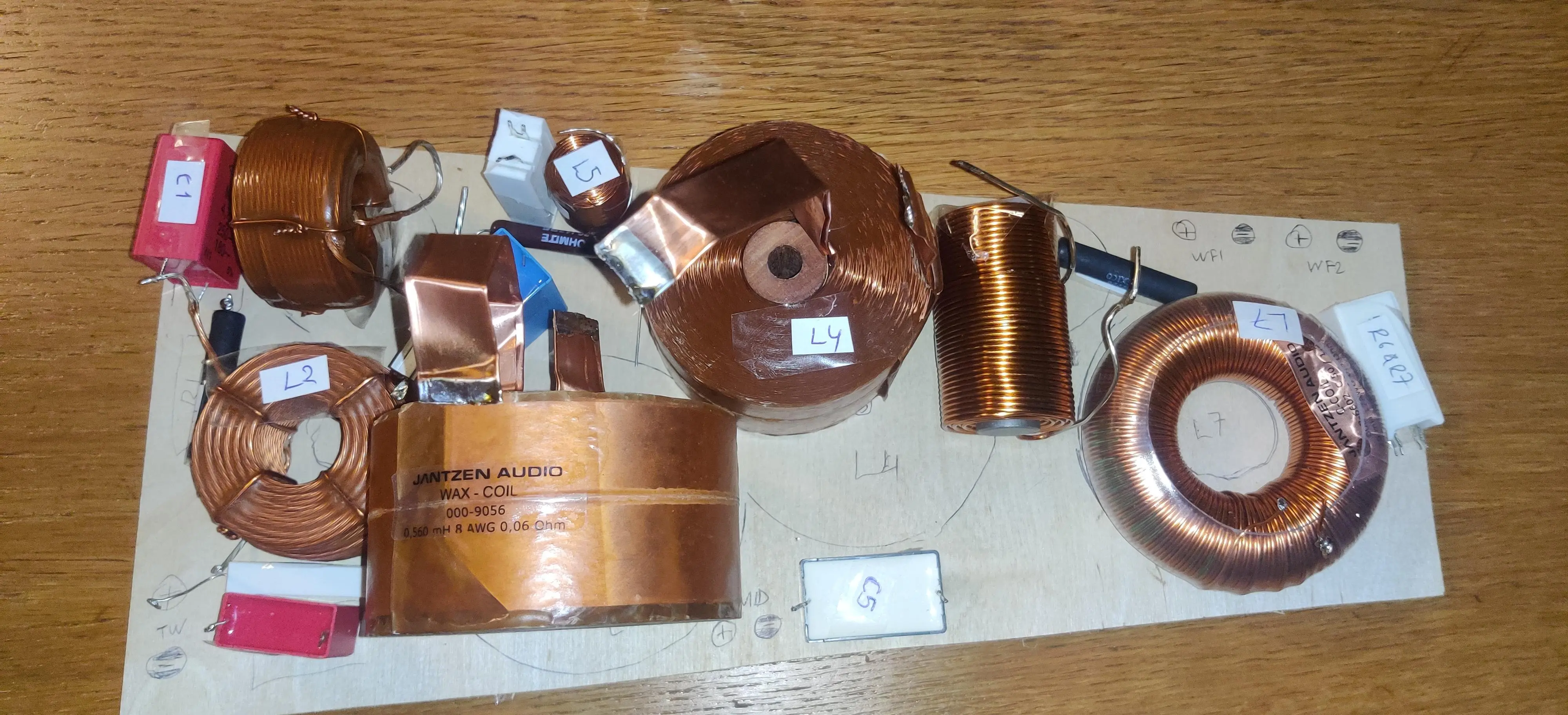
Damn, those Jantzen foil caps cost a fortune at that size. There’s so much copper on that board that three different methheads have tried to steal OP’s post.
Is this for a 3 or 4-way speaker? As others mentioned, you can break the board into more than one piece by driver. You know which components are for which driver by the outputs, but also generally, there should be segments of the individual networks with one pair of wires from the up / downstream network in and one pair out to a driver.
Since you know where the connections and components connect to each other, you can untangle networks and spread / split the board with some alligator wires to visualize it better. Get some of these: https://www.amazon.com/WGGE-WG-026-Pieces-Colors-Alligator/dp/B06XX25HFX/ and start stretching things across a table. Color coding helps. Use a single wire of a specific color to symbolize each of the drivers and input rails. Also the boots are removeable / swappable and take well to sharpies, so you can mark polarity.